Replacing IR remote
I've picked up a few LED floodlights that can do various colours (and some effects) controlled by IR remotes. They have their uses as they are - but I want to replace the IR remotes with something connected to a computer so I can have random programs control them.
Getting IR codes
The first thing I wanted to do was record the IR codes that the remote was sending.
I found some stuff on using lirc on a pi, so cut one of the IR receivers off a light and hooked it up to a pi and recorded the codes from the remote. That gave a lirc config file with the codes.
I used keysims KEY_A through KEY_X for the buttons on the remote starting at the top left going across the top row, then down to the next. So KEY_C is off, KEY_D is on, down to KEY_X in the bottom right for smooth.
Sending IR codes
When I started messing with this I thought I could use lirc's ability to send codes by wiring the output pin from the pi to the signal line going into the light and all would be good. I tried it and it didn't work. I thought the issue might be that the two had a different ground so the signal wasn't at the right level. I tried solving that by connecting the light and pi's grounds to each other. That switched the pi off. Luckilly it came back on, apparently none the worse for wear, once I disconnected them again. I guess they were at different levels, by enough to upset the pi's power stuff.
I decided I needed some output isolation. I was sure I had some optocouplers around somewhere, but couldn't find them, so I ordered some more.
While waiting for them to turn up I had a look at the datasheet for the IR receiver and discovered that it did more than just pass the IR signal to it's output. Turns out IR remotes have a carrier (38kHz for this one) that they send, or don't, for periods of time to send things. The receiver gives a constant low when it sees the carrier and a constant high the rest of the time.
Since lirc was set up to be sending the carrier via an IR LED the signal it was outputting wouldn't match what the light was expecting to get from the receiver module.
I considered changing lirc's output, or building a circuit to do the transform the receiver module was doing (a low pass filter and an inverter? would a cap and a transistor be enough?), but opted for swapping the pi out for an arduino to generate the right waveform since I know what I'm doing there a lot better than getting into the lirc code or doing anything analogue.
I just needed to figure out what the right waveform was from the lirc config file.
I read a bit about how IR command frames work (on sites that I can't find now...). Short version is that there are a few encoding schemes the SPACE_ENC on the flags line tells us we need pulse space encoding: the length of the gap between pulses determines if it's a 1 or a 0. The timing for each of those is on the one and zero lines; first number gives the length of the pulse, second one the length of the space before the next bit (both in microseconds). We also have a header (or in some descriptions: preamble) of one longer than normal pulse followed by a longer than normal space. Timings for those are on the header line. After the header will come the 16 pre_data_bits, which pre_data line says should be 0xF7. Then the 16 actual data bits - which will vary depending on which of the codes we want to send. The frame then concludes with a trailing pulse (timing from ptrail) and then a minimum period before the next code should be sent (gap).
I couldn't find anything to say what the bit ordering should be. I decided I'd try "most significant bit first" first, then "least significant bit first", then the variation on byte vs bit ordering till I got an ordering that worked (or ran out of ways to reorder them and would have to go looking for something else that might be wrong). As it turned out "most significant bit first" was actually right, so didn't need to try any of the others.
This figuring out had taken long enough that the optocouplers I ordered had turned up, so I decided to try doing things properly and isolate the light from the arduino. If figured I could also use this to invert the signal from the arduino so I can write the code with the output normally being low and going high for pulses. That's the way round I think of as normal so it reduces the chance of me getting bugs from getting it the wrong way round somewhere. I hooked up the optocoupler like this:
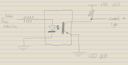
The current limiting resistor between the arduino and the optocoupler is something about 220Ω, and the pull up on the light side is about 10kΩ so we don't get very much current there.
Then I just needed a sketch to send commands. This is very rough still; the command it sends is hard coded and it just loops sending it over and over. But it does work - I can switch a light on and off with it.
Next steps
I need to update the arduino sketch to allow the commands to be sent in (probably over serial). Then add support for more lights. Then I need to figure out something to actually do with a few computer controlled RGB floodlights...